SLM-ACDCI-8NP-RLY8#
Description#
8 fast response inputs for 24 VAC/VDC sink/source.
8 relay outputs rated for 120VAC operation.
Two isolated commons for flexible wiring.
Configuration#
No configuration required
Modbus Mapping#
Note
The following register mappings are based on a single-module configuration. Actual mappings may differ based on the physical slot arrangement in your system.
Input Register Mapping#
Channel |
Modbus Input Status Register |
Common Terminal |
Access |
|---|---|---|---|
IN1 |
10001 |
C1 |
Read-Only |
IN2 |
10002 |
C1 |
Read-Only |
IN3 |
10003 |
C1 |
Read-Only |
IN4 |
10004 |
C1 |
Read-Only |
IN5 |
10005 |
C1 |
Read-Only |
IN6 |
10006 |
C1 |
Read-Only |
IN7 |
10007 |
C1 |
Read-Only |
IN8 |
10008 |
C1 |
Read-Only |
Output Register Mapping#
Channel |
Modbus Input Status Register |
Common Terminal |
Access |
|---|---|---|---|
OUT1 |
00001 |
C2 |
Read/Write |
OUT2 |
00002 |
C2 |
Read/Write |
OUT3 |
00003 |
C2 |
Read/Write |
OUT4 |
00004 |
C2 |
Read/Write |
OUT5 |
00005 |
C2 |
Read/Write |
OUT6 |
00006 |
C2 |
Read/Write |
OUT7 |
00007 |
C2 |
Read/Write |
OUT8 |
00008 |
C2 |
Read/Write |
Notes:
Inputs (IN1-IN8) are read-only and correspond to Modbus Input Status Registers (10001 - 10008).
Outputs (OUT1-OUT8) are read/write and correspond to Modbus Coil Registers (00001 - 00008).
Example Usage#
Note
The following examples assume that it is the only module connected. Actual mapping may vary depending on the configuration of the system.
import time
from pyModbusTCP.client import ModbusClient
import struct

client_ip = '192.168.1.255'  # Replace with your device's IP
client = ModbusClient(host=client_ip, port=502, auto_open=True)

# Read all 8 inputs
inputs = client.read_discrete_inputs(address=0, count=8)
print("Inputs:", inputs)

# Write to outputs
client.write_single_coil(0, True)  # Turn on output 1
client.write_multiple_coils(1, [True, False, True, False, True, False, True, True])  # Pattern for outputs 2-8
Note
This is an explanatory section on how to read/write to a module. For a more complete example using Python, visit Python Example.
#include <ArduinoModbus.h> // Include Modbus library

// Assume ModbusRTUClient is already initialized (e.g., ModbusRTUClient.begin(...))
int slaveId = 0x01;       // The ID of the Modbus slave device
int inputStartAddress = 0;     // The starting address of the inputs
int outputStartAddress = 0;    // The starting address of the outputs
int numInputs = 8;            // The number of inputs to read
int numOutputs = 8;           // The number of outputs to write

void setup() {
    # Setup modbus client
}

void loop() {
    // Read inputs
    uint16_t inputs[numInputs];
    ModbusRTUClient.requestFrom(slaveId, INPUT_STATUS, inputStartAddress, numInputs);
    for (int i = 0; i < numInputs; i++) {
        inputs[i] = ModbusRTUClient.read();
    }

    // Write to outputs
    ModbusRTUClient.beginTransmission(slaveId, COILS, outputStartAddress, numOutputs);
    for (int i = 0; i < numOutputs; i++) {
        ModbusRTUClient.write(i % 2);  // Alternate pattern
    }
    ModbusRTUClient.endTransmission();

    delay(1000);
}
Note
The above code uses the ArduinoModbus library and is not a complete program.
Note
This is an explanatory section on how to read/write to a module. For a more complete example using Arduino, visit Arduino Example.
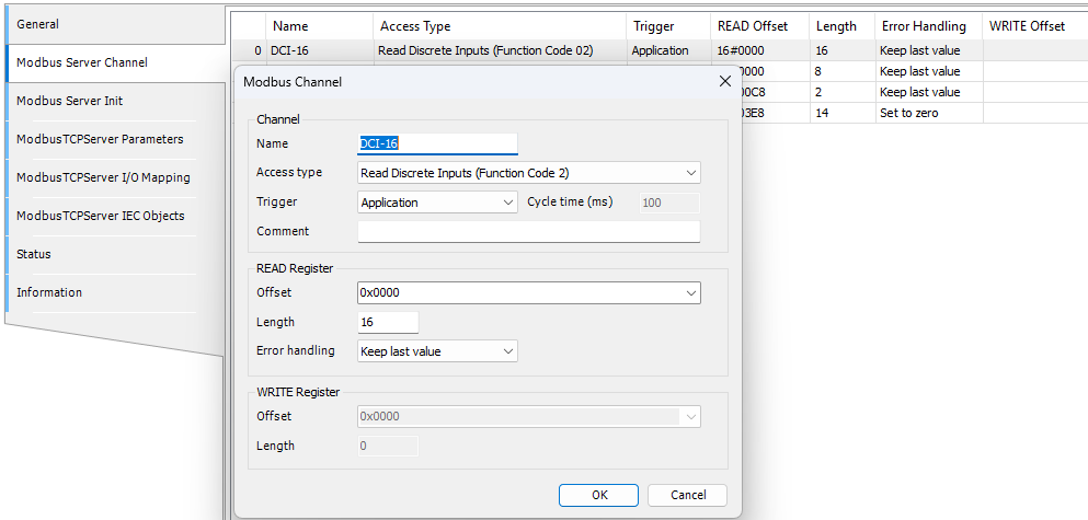
Under Modbus_TCP_Server -> Modbus Server Channel
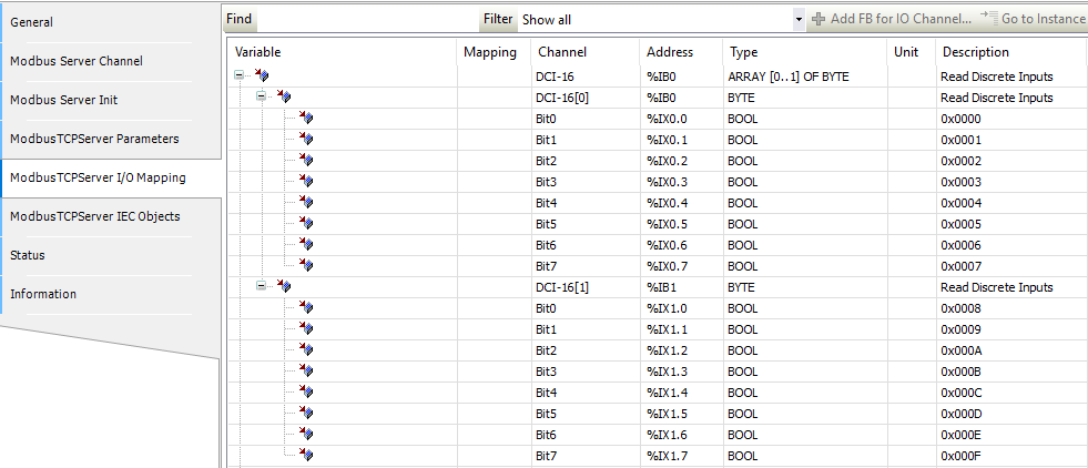
 Under Modbus_TCP_Server -> Modbus Server Channel -> I/O Mapping
 Usage
Usage
VAR
    // Inputs
    DCI8_1 AT %IB0 : BYTE;
    DCICH1 AT IX0.0 : BOOL;
    DCICH2 AT IX0.1 : BOOL;
    DCICH3 AT IX0.2 : BOOL;
    DCICH4 AT IX0.3 : BOOL;
    DCICH5 AT IX0.4 : BOOL;
    DCICH6 AT IX0.5 : BOOL;
    DCICH7 AT IX0.6 : BOOL;
    DCICH8 AT IX0.7 : BOOL;

    // Outputs
    DCO7_1 AT %QB0 : BYTE;
    DCOCH1 AT QX0.0 : BOOL;
    DCOCH2 AT QX0.1 : BOOL;
    DCOCH3 AT QX0.2 : BOOL;
    DCOCH4 AT QX0.3 : BOOL;
    DCOCH5 AT QX0.4 : BOOL;
    DCOCH6 AT QX0.5 : BOOL;
    DCOCH7 AT QX0.6 : BOOL;
    DCOCH8 AT QX0.7 : BOOL;
END_VAR
Note
This is an explanatory section on how to read/write to a module. For a more complete example using Codesys, visit Codesys Example.
Tag
Tag Name |
Type |
|---|---|
DI1 |
Boolean |
DI2 |
Boolean |
DI3 |
Boolean |
DI4 |
Boolean |
DI5 |
Boolean |
DI6 |
Boolean |
DI7 |
Boolean |
DI8 |
Boolean |
DO1 |
Boolean |
DO2 |
Boolean |
DO3 |
Boolean |
DO4 |
Boolean |
DO5 |
Boolean |
DO6 |
Boolean |
DO7 |
Boolean |
DO8 |
Boolean |
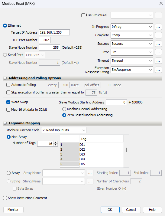
Usage
Note
This is an explanatory section on how to read/write to a module. For a more complete example using Productivity Suite, visit Productivity Suite Example.
Safety Precautions#
Do not add or remove modules while field power is applied.
Ensure proper grounding and wire connections to prevent electrical hazards.
Follow all local and national electrical codes.
Maintain adequate ventilation to prevent overheating.
For more details and technical support, visit Synergy Logic or contact support@synergy-logic.com.