OpenPLC Example Project#
Project Overview#
This project progressively activates the digital outputs of two slots. The purpose behind it is to better demonstrate how the modbus addresses mapped in the SLM-MX are sequential.
Before you Start
Before you start, please ensure you have the following:
SLM-MX configured and connected to your network
Basic knowledge of Ladder logic
Basic knowledge of Structured Text programming
Project Files#
The OpenPLC project file, as well as the SLM-MX configuration file can be found in the rar file here.
Please download and extract the zip file to a easily accessible directory.
Hardware Configuration#
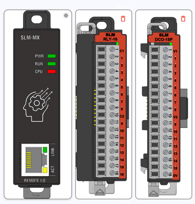
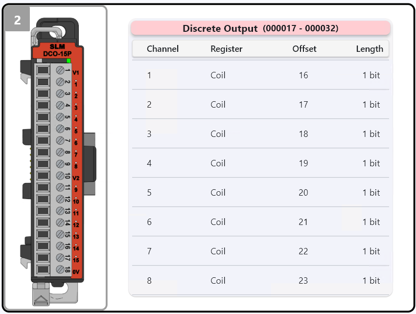
The slots used in this example were the same as those shown in the photo above.
Module 1: SLM-RLY-16 Module 2: SLM-DCO-15p
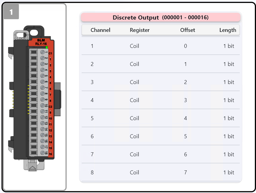
Module Configuration#
For the example to work correctly, your MX must have the respective slots connected. After that, click the configure button so that the MX maps the slots found in the Modbus register table.
Software Configuration#
The version of the OpenPLC Editor used is the 3.0 release: 2024-02-05.
The version of the OpenPLC RunTime used is the Windows version.
The target platform is a Windows 10 machine running OpenPLC Editor/RunTime, essentially using the PC as the main controller with the SLM-MX as the remote I/O module.
Importing the Project#
Open the OpenPLC Editor and click on Open. Navigate to the folder you downloaded and extracted — inside it, you will find a file named project. Select this file and click Open to load the project.
After importing, the project tab should contain the following elements:
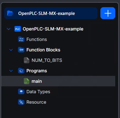
Double-clicking on main will allow you to view the Ladder programming created for this simple project.
At the top left corner, there is a button with a downward arrow responsible for exporting the file that we will use in the OpenPLC RunTime.
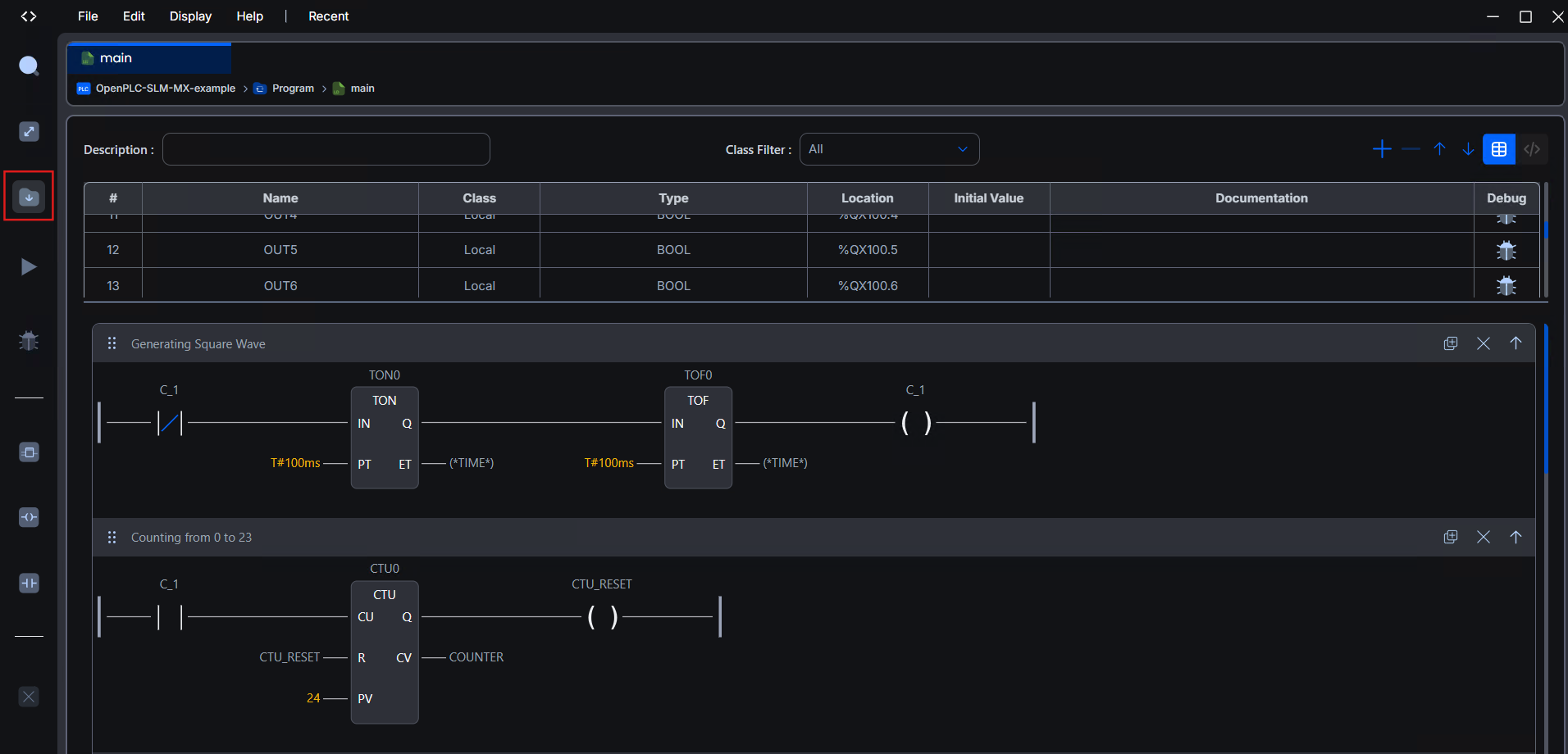
Note: This file has also been made available in the RAR archive, so feel free to use it without needing to export another one.
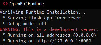
Setup OpenPLC Runtime#
After installation, open the runtime, and you will notice that it launches a terminal displaying the access address. For this example, we used Chrome Version 134.0.6998.89.
When accessing the address shown in the terminal, a login screen will appear. If this is your first time using it, the default values are:
username: openplc
password: openplc
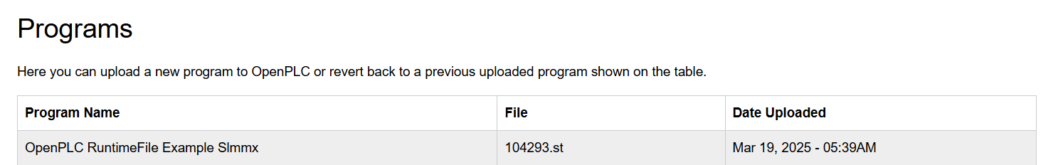
In the Programs tab, click Choose File, select the provided program.st file or the one you generated in the OpenPLC Editor, and then click Upload Program. A brief compilation will occur, and shortly after, the program will be listed in the previously loaded programs table.
Now, go to the Slave Devices -> Add new device tab and let’s configure the SLM-MX so that it is recognized by the OpenPLC RunTime.
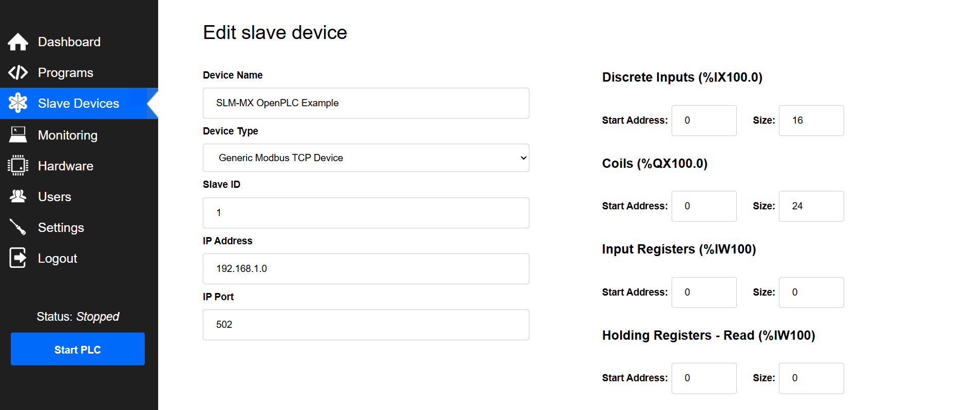
Device name: A friendly label to recognize your device among the configured devices.
Device type: Select Generic Modbus TCP Device.
Slave ID: Since we are dealing with a Modbus TCP connection, this parameter is not necessary, but by default, we leave it at 1.
IP Address: Set the current IP address that your SLM-MX has on the network.
Port: Default for Modbus TCP is 502.
On the right side, under Coils, set the Start address to 0 and the Size to 24 (since, in this example, we switch the first 24 coil registers).
After this, just click Save Device and all the parameters will be ready to run the example.
Running Example#
Attention: In this example, the first 24 coils of the MX will be activated sequentially, so take appropriate precautions if there is any load connected to these channels.
After completing all the previous steps, click the Start PLC button in the side menu at the bottom.
Below is the translated and reformatted version of your project description. The formatting uses several Jupyter Book content blocks (e.g., dropdowns and admonitions) to enhance clarity and organization.
Project Breakdown#
This project contains the following entities:
Variable Table
# |
Name |
Type |
Location |
|---|---|---|---|
1 |
TON0 |
BOOL |
- |
2 |
TOF0 |
BOOL |
- |
3 |
C_1 |
BOOL |
- |
4 |
CTU_RESET |
BOOL |
- |
5 |
COUNTER |
INT |
- |
6 |
CTU0 |
BOOL |
- |
7 |
OUT0 |
BOOL |
%QX100.0 |
8 |
OUT1 |
BOOL |
%QX100.1 |
9 |
OUT2 |
BOOL |
%QX100.2 |
10 |
OUT3 |
BOOL |
%QX100.3 |
11 |
OUT4 |
BOOL |
%QX100.4 |
12 |
OUT5 |
BOOL |
%QX100.5 |
13 |
OUT6 |
BOOL |
%QX100.6 |
14 |
OUT7 |
BOOL |
%QX100.7 |
15 |
OUT8 |
BOOL |
%QX101.0 |
16 |
OUT9 |
BOOL |
%QX101.1 |
17 |
OUT10 |
BOOL |
%QX101.2 |
18 |
OUT11 |
BOOL |
%QX101.3 |
19 |
OUT12 |
BOOL |
%QX101.4 |
20 |
OUT13 |
BOOL |
%QX101.5 |
21 |
OUT14 |
BOOL |
%QX101.6 |
22 |
OUT15 |
BOOL |
%QX101.7 |
23 |
OUT16 |
BOOL |
%QX102.0 |
24 |
OUT17 |
BOOL |
%QX102.1 |
25 |
OUT18 |
BOOL |
%QX102.2 |
26 |
OUT19 |
BOOL |
%QX102.3 |
27 |
OUT20 |
BOOL |
%QX102.4 |
28 |
OUT21 |
BOOL |
%QX102.5 |
29 |
OUT22 |
BOOL |
%QX102.6 |
30 |
OUT23 |
BOOL |
%QX102.7 |
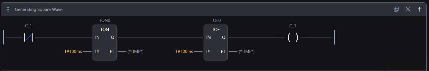
Square Wave Generator#
The first part of the ladder code creates a square wave generator. It toggles the boolean variable blink_led every 100ms, switching its state between true and false.
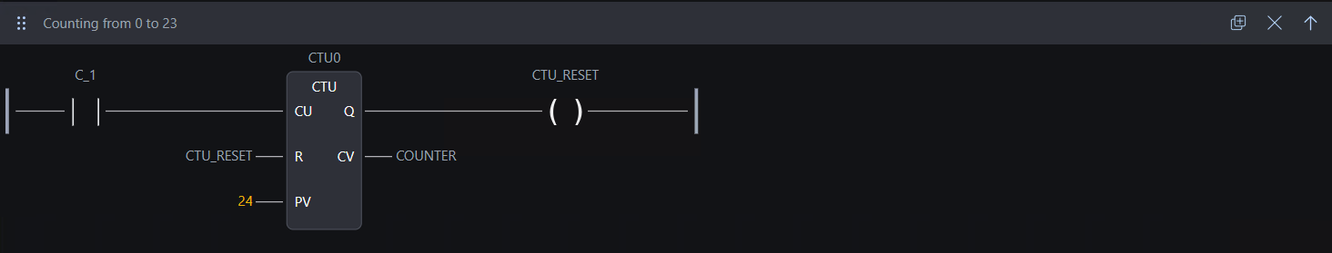
Counter#
The second part of the code implements a counter with a maximum limit of 24 (i.e., counts from 0 to 23). This counter increments every time blink_led is true, thereby increasing the counter variable. Upon reaching the twenty-fourth increment, the Q OUTput is activated, which resets the count.
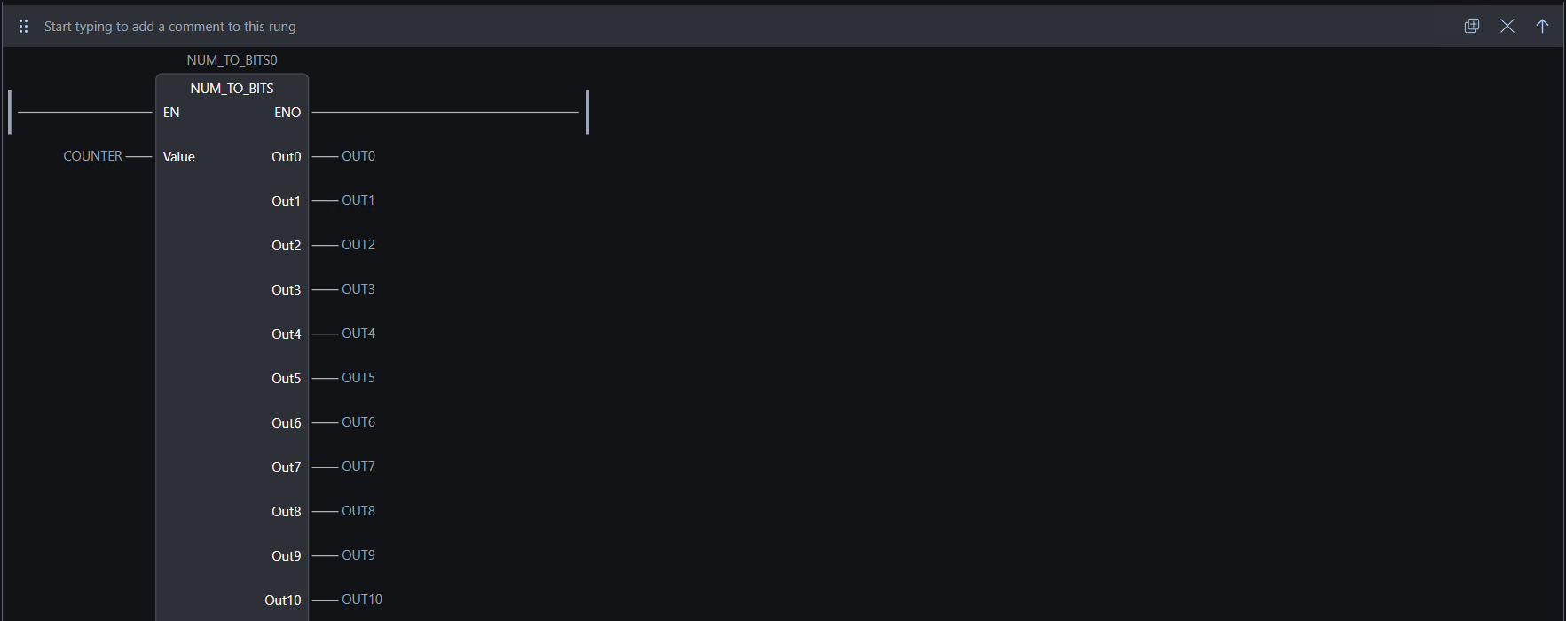
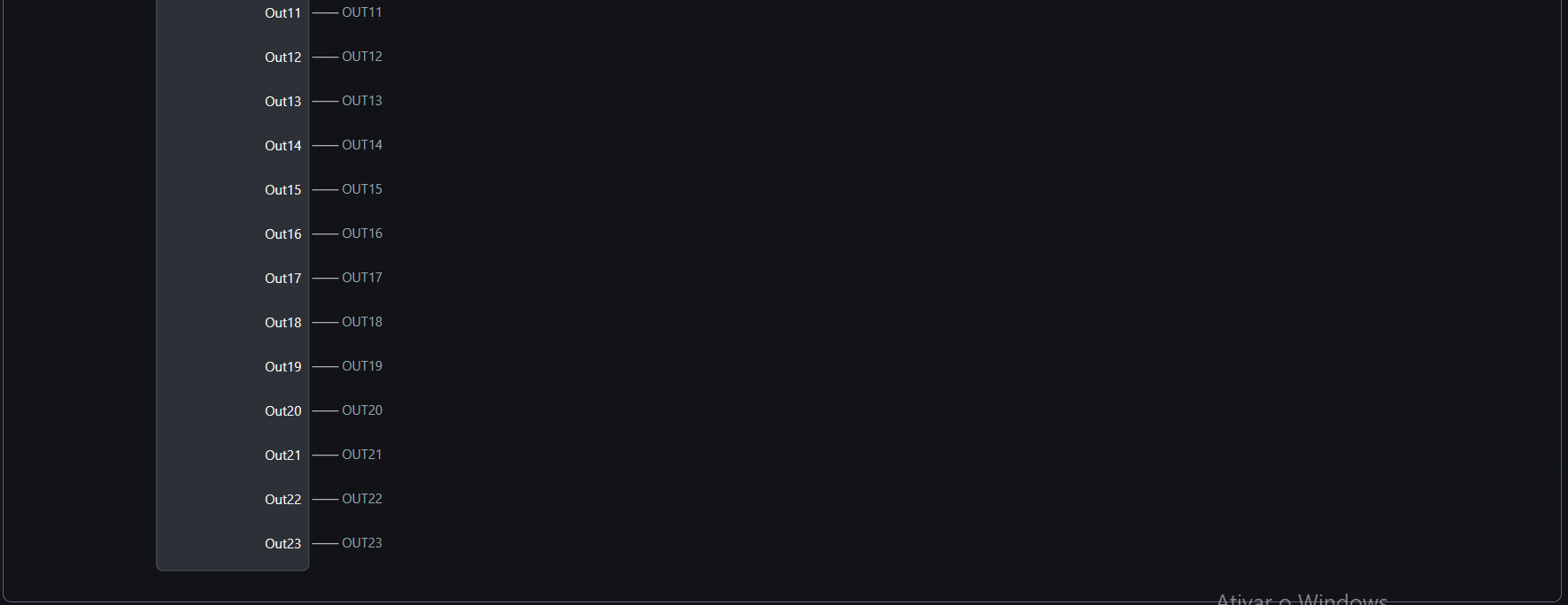
Custom Function Block: num_to_bits#
For this specific example, a custom function block called num_to_bits is created. Its purpose is to read an input value and activate only the corresponding OUTput. For example, when the input is 0, OUT0 is enabled; when it is 5, OUT5 is enabled; and so on.