SLM-AI4-AO2-mA#
Description#
4-channel 0-20mA input and 2-channel 4-20mA output module.
13-bit Resolution for precision control on both inputs and outputs
Designed for industrial control applications.
Configuration#
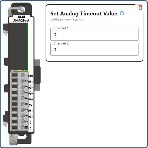
Channel Select
Enable or disable the channels to be read/written. The first channel of each type cannot be disabled.
Modbus Mapping#
Note
The following register mappings assumes that it is the only module connected. Actual mapping may vary depending on the configuration of the system.
Input Register Mapping#
Channel |
Modbus Register |
Access |
Register Type |
Data Length |
|---|---|---|---|---|
Ch1 |
30001 |
Read-Only |
Input Register |
16-bit |
Ch2 |
30002 |
Read-Only |
Input Register |
16-bit |
Ch3 |
30003 |
Read-Only |
Input Register |
16-bit |
Ch4 |
30004 |
Read-Only |
Input Register |
16-bit |
Output Register Mapping#
Channel |
Modbus Register |
Access |
Register Type |
Data Length |
|---|---|---|---|---|
Ch1 |
40001 |
Read/Write |
Holding Register |
16-bit |
Ch2 |
40002 |
Read/Write |
Holding Register |
16-bit |
Notes:
Each Modbus Input Register corresponds to a single analog input channel.
Each Modbus Holding Register corresponds to a single analog output channel.
0-20mA inputs are read-only and mapped to Modbus Input Registers (30001 - 30004).
4-20mA outputs are read/write and mapped to Modbus Holding Registers (40001 - 40002).
Input values range from 0-8191 corresponding to 0-20mA input.
Output values range from 0-8191 corresponding to 4-20mA output.
Status Register Mapping#
Note: The status registers are read-only booleans and are mapped to Discrete Input Status registers (101001 - 101010).
Status |
Modbus Register |
Access |
Register Type |
Data Length |
|---|---|---|---|---|
Module diagnostics failure |
101001 |
Read-Only |
Discrete Input Status |
1-bit |
24V Missing |
101002 |
Read-Only |
Discrete Input Status |
1-bit |
AI Ch1 Under Range |
101003 |
Read-Only |
Discrete Input Status |
1-bit |
AI Ch2 Under Range |
101004 |
Read-Only |
Discrete Input Status |
1-bit |
AI Ch3 Under Range |
101005 |
Read-Only |
Discrete Input Status |
1-bit |
AI Ch4 Under Range |
101006 |
Read-Only |
Discrete Input Status |
1-bit |
AI Ch1 Over Range |
101007 |
Read-Only |
Discrete Input Status |
1-bit |
AI Ch2 Over Range |
101008 |
Read-Only |
Discrete Input Status |
1-bit |
AI Ch3 Over Range |
101009 |
Read-Only |
Discrete Input Status |
1-bit |
AI Ch4 Over Range |
101010 |
Read-Only |
Discrete Input Status |
1-bit |
Example Usage#
Note
The following examples assume that it is the only module connected. Actual mapping may vary depending on the configuration of the system.
import time
from pyModbusTCP.client import ModbusClient
import struct

client_ip = '192.168.1.255'  # Replace with your device's IP
client = ModbusClient(host=client_ip, port=502, auto_open=True)

# Convert 0-20mA to 0-8191 (input)
def mA_to_raw_input(mA):
    return int(mA * (8191 / 20))

# Convert 0-8191 to 0-20mA (input)
def raw_to_mA_input(raw):
    return raw * (20 / 8191)

# Convert 4-20mA to 0-8191 (output)
def mA_to_raw_output(mA):
    return int((mA - 4) * (8191 / 16))

# Convert 0-8191 to 4-20mA (output)
def raw_to_mA_output(raw):
    return 4 + (raw * (16 / 8191))

# Read all input values
input_raw = client.read_input_registers(0, 4)  # Read 4 inputs
input_mA = [raw_to_mA_input(x) for x in input_raw]
print("Input currents:", input_mA)

# Set both outputs
output_values = [12.0, 16.0]  # Set to 12mA and 16mA
raw_values = [mA_to_raw_output(v) for v in output_values]
client.write_multiple_registers(0, raw_values)  # Write to both outputs

# Read current output values
current_raw = client.read_holding_registers(0, 2)  # Read both outputs
current_mA = [raw_to_mA_output(x) for x in current_raw]
print("Current outputs:", current_mA)
Note
This is an explanatory section on how to read/write to a module. For a more complete example using Python, visit Python Example.
#include <ArduinoModbus.h> // Include Modbus library

// Assume ModbusRTUClient is already initialized (e.g., ModbusRTUClient.begin(...))
int slaveId = 0x01;       // The ID of the Modbus slave device
int inputStartAddress = 0;     // The starting address of the input registers
int outputStartAddress = 0;    // The starting address of the output registers
int numInputs = 4;            // The number of inputs to read
int numOutputs = 2;           // The number of outputs to write

void setup() {
    # Setup modbus client
}

void loop() {
    // Read all inputs
    ModbusRTUClient.requestFrom(slaveId, INPUT_REGISTERS, inputStartAddress, numInputs);
    float inputCurrents[4];
    for (int i = 0; i < numInputs; i++) {
        int rawValue = ModbusRTUClient.read();
        inputCurrents[i] = map(rawValue, 0, 8191, 0, 20);  // Convert to 0-20mA
        // Process current value
    }

    // Write to both outputs
    float outputCurrents[2] = {12.0, 16.0};  // Set to 12mA and 16mA
    int outputValues[2];
    for (int i = 0; i < numOutputs; i++) {
        outputValues[i] = map(outputCurrents[i], 4, 20, 0, 8191);  // Convert 4-20mA to raw
    }

    ModbusRTUClient.beginTransmission(slaveId, HOLDING_REGISTERS, outputStartAddress, numOutputs);
    for (int i = 0; i < numOutputs; i++) {
        ModbusRTUClient.write(outputValues[i]);
    }
    ModbusRTUClient.endTransmission();

    delay(1000);
}
Note
The above code uses the ArduinoModbus library and is not a complete program.
Note
This is an explanatory section on how to read/write to a module. For a more complete example using Arduino, visit Arduino Example.
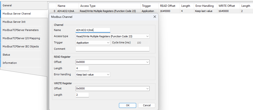
Under Modbus_TCP_Server -> Modbus Server Channel
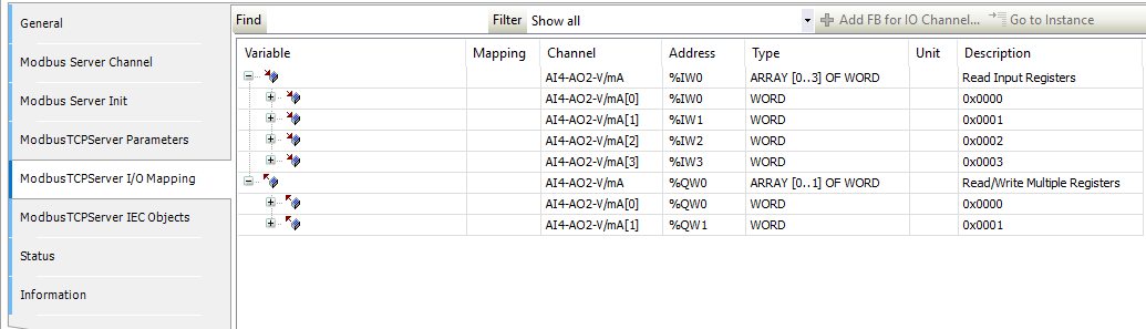
 Under Modbus_TCP_Server -> Modbus Server Channel -> I/O Mapping
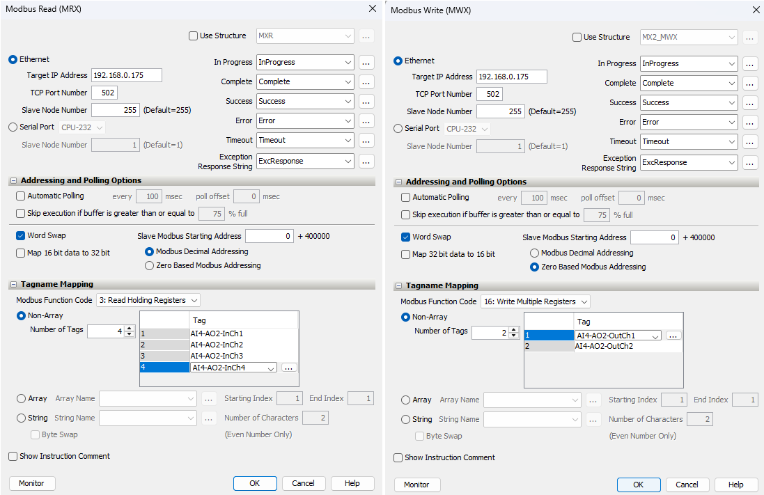
 Usage
Usage
VAR
    // Inputs
    AI1 AT %IW0 : WORD;
    AI2 AT %IW1 : WORD;
    AI3 AT %IW2 : WORD;
    AI4 AT %IW3 : WORD;

    // Outputs
    AO1 AT %QW0 : WORD;
    AO2 AT %QW1 : WORD;

    // Converted values
    InputCurrents : ARRAY[1..4] OF REAL;
    OutputCurrents : ARRAY[1..2] OF REAL;
END_VAR

// Convert raw values to currents (0-20mA for inputs)
InputCurrents[1] := WORD_TO_REAL(AI1) * 20.0 / 8191.0;
InputCurrents[2] := WORD_TO_REAL(AI2) * 20.0 / 8191.0;
InputCurrents[3] := WORD_TO_REAL(AI3) * 20.0 / 8191.0;
InputCurrents[4] := WORD_TO_REAL(AI4) * 20.0 / 8191.0;

// Convert currents to raw values and write to outputs (4-20mA for outputs)
AO1 := REAL_TO_WORD((OutputCurrents[1] - 4.0) * 8191.0 / 16.0);
AO2 := REAL_TO_WORD((OutputCurrents[2] - 4.0) * 8191.0 / 16.0);
Note
This is an explanatory section on how to read/write to a module. For a more complete example using Codesys, visit Codesys Example.
Tag
Tag Name |
Type |
|---|---|
AI1 |
Integer, 16 Bit |
AI2 |
Integer, 16 Bit |
AI3 |
Integer, 16 Bit |
AI4 |
Integer, 16 Bit |
AO1 |
Integer, 16 Bit |
AO2 |
Integer, 16 Bit |
Usage
Ladder Logic Example
Network 1: Read Inputs
[AI1] -> [Scale] -> [InputCurrent1]  // Scale 0-8191 to 0-20mA
[AI2] -> [Scale] -> [InputCurrent2]
[AI3] -> [Scale] -> [InputCurrent3]
[AI4] -> [Scale] -> [InputCurrent4]

Network 2: Write Outputs
[OutputCurrent1] -> [Scale] -> [AO1]  // Scale 4-20mA to 0-8191
[OutputCurrent2] -> [Scale] -> [AO2]
Note
This is an explanatory section on how to read/write to a module. For a more complete example using Productivity Suite, visit Productivity Suite Example.
Specifications#
Safety Precautions#
Do not add or remove modules while field power is applied.
Ensure proper grounding and wire connections to prevent electrical hazards.
Follow all local and national electrical codes.
Maintain adequate ventilation to prevent overheating.
For more details and technical support, visit Synergy Logic or contact support@synergy-logic.com.