CODESYS Example Project#
Project Overview#
The project simulates a temperature-controlled system where the temperature reading from the SLM-THM-4 is used to control the SLM-RLY-16 relays.
The core function maps a temperature range (75°F - 125°F) to the 16 relay channels, creating a bar-graph representation of the temperature as each relay channel corresponds to an LED.
Before you Start
Before you start, please ensure you have the following:
CODESYS Control Win V3 x64 installed
SLM-MX configured and connected to your network
Basic knowledge of CODESYS Control Win V3 x64
Basic knowledge of Structured Text programming
Project Files#
The CODESYS project file, as well as the SLM-MX configuration file can be found in the zip file here.
Please download and extract the zip file to an easily accessible directory.
Hardware Configuration#
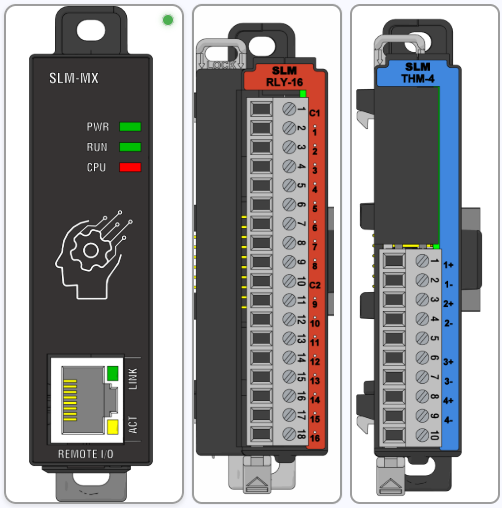
There are two modules used:
Module 1: SLM-RLY-16
Module 2: SLM-THM-4
Module Configuration#
Inside the extracted zip file, there should be a file called THMDemo.slmmx. This is the SLM-MX configuration file to import into the SLM-MX Configurator.
Please refer to the Importing Configuration Files page for instructions on how to import the configuration file.
Software Configuration#
The version of CODESYS used for this project is 3.5 SP20 Patch 5.
The target platform is a Windows 11 machine running CODESYS Control Win V3, essentially using the PC as the main controller with the SLM-MX as the remote I/O module.
This also keeps the project easy to deploy to any PC with CODESYS installed.
Importing the project#
You can import the project by first extracting the zip file into a easily accessible directory.
Then, start CODESYS and create a new Project.
Select the Standard Project and save the project in any location you wish .
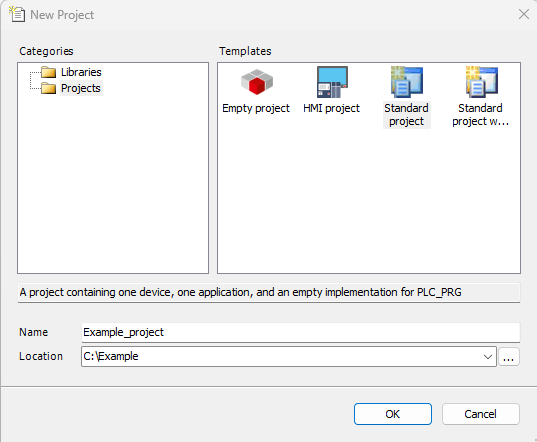
Set the device type to CODESYS Control Win V3, and PLC_PRG as anything (Structured Text as default).
Next, on the device tree on the left, click on the project name at the top of the tree to highlight it, and select Project -> Import Project.
Make sure to select the ‘THMDEMO.export’ file in the extracted zip file. With everything highlighted, press ‘OK’ to import the project.
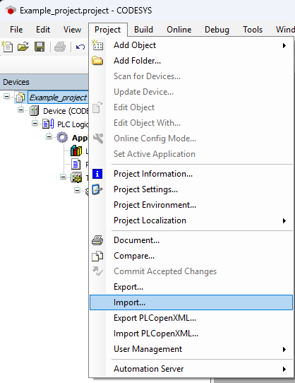
With the project imported, you should see the modules in the device tree.
Project Configuration#
Device (CODESYS Control Win V3 x64)#
This refers to the device the project is being built for. In this case, it is a PC running CODESYS Control Win V3 x64. For more information on the CODESYS Control Win V3 x64, please refer to the CODESYS Control Setup Guide page.
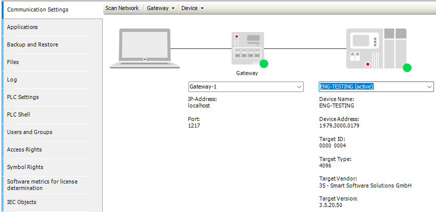
Just make sure that your device is connected under the Communication Settings tab.
Ethernet#
This is the network device that will be used to connect to the SLM-MX. It is vital that your Device is recognized so that you can select a Network Interface, which automatically populates the IP Address and Subnet Mask.
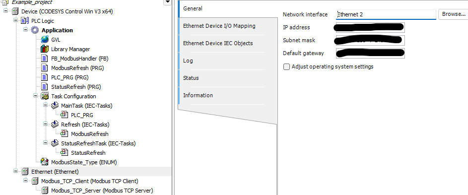
Underneath the Ethernet are the Modbus_TCP_Client and Modbus_TCP_Server items. The only thing to configure here is the Server IP address under the Modbus_TCP_Server item. This should be set to your SLM-MX IP address.
Modbus Mapping#
The Modbus addresses for the SLM-MX have already been defined under Ethernet -> Modbus_TCP_Client -> Modbus_TCP_Server -> Modbus Server Channel.
Channel |
Name |
Access Type |
Trigger |
READ Offset |
Length |
Error Handling |
WRITE Offset |
Length |
|---|---|---|---|---|---|---|---|---|
0 |
RLY-16 |
Write Multiple Coils (Function 15) |
Application |
16#0000 |
16 |
|||
1 |
THM-4 |
Read Input Registers (Function 04) |
Application |
16#0000 |
8 |
Keep last value |
||
2 |
SLM-STATUS |
Read Holding Registers (Function 03) |
Application |
16#00C3 |
2 |
Keep last value |
||
3 |
THM-4-STATUS |
Read Input Registers (Function 04) |
Application |
16#03E8 |
14 |
Set to zero |
Important Considerations
Trigger Type: All Modbus channels are triggered by the “Application.” Avoid using cyclical triggers. Cyclical triggers can lead to performance timing issues, potentially resulting in race conditions where data is not read or written accurately.
READ and WRITE offsets: Please note the READ and WRITE offsets are the offsets from the modbus address table for the SLM-MX.
I/O Mapping#
The I/O mapping is done under Modbus_TCP_Server -> ModbusCPServer I/O Mapping.
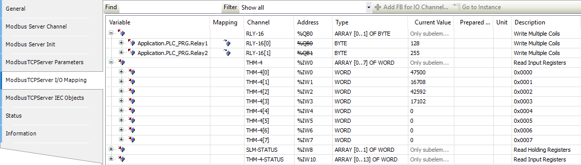
Here, RLY-16[0] and RLY-16[1] are directly mapped to the PLC_PRG’s Relay1 and Relay2 variables.
The other channels are not mapped and can be accessed through the IEEE format registers.
For example for the THM-4, I can access the 32-bit float value of channel 1 with THMCH1 AT %IW0 : REAL;
Project Structure#
The CODESYS project implements a temperature monitoring system that controls relays based on temperature readings. The project is organized with the following components:
Data Structures
GVL (Global Variables): Contains shared variables for Modbus communication control, temperature values, and status information
ModbusState_Type (ENUM): Defines states for the Modbus communication state machine
Function Blocks
FB_ModbusHandler (FB): Manages Modbus communication using a state machine
Programs
ModbusRefresh (PRG): Handles Modbus communication cycles using multiple FB_ModbusHandler instances (10ms cycle)
PLC_PRG (PRG): Main program that processes temperature data and controls relay outputs (200ms cycle)
StatusRefresh (PRG): Updates THM registers and status registers (20ms cycle)
Global Variables (GVL)#
The GVL contains the global variables for the project.
GVL Structured Text
VAR_GLOBAL
	EnableModbusWrite : BOOL := FALSE;
	EnableModbusRead : BOOL := FALSE;
	EnableModbusStatus : BOOL := FALSE;
    WriteChannelIndex : INT;  // Set by application
    ReadChannelIndex : INT;   // Set by application
	StatusChannelIndex : INT;

	THM_CH : ARRAY [0..7] OF WORD;
	THM_STATUS : ARRAY [0..13] OF WORD;
END_VAR
Variable Explanation#
EnableModbusWrite/Read/Status: Boolean to enable/disable Modbus write/read/status operations from FB_ModbusHandler.Write/Read/StatusChannelIndex: Index of the write/read/status channel to be used.THM_CH: Array of words to store the temperature values.THM_STATUS: Array of words to store the temperature status values.
Enum (ModbusState_Type)#
The ModbusState_Type enum is used to define the state of the Modbus communication.
ModbusState_Type Structured Text
TYPE ModbusState_Type :
(
	Idle,
	StartOperation,
	WaitForCompletion,
	ErrorState
);
END_TYPE
States:#
IdleStartOperationWaitForCompletionErrorState
These states are used in the FB_ModbusHandler state machine to determine the current state of the Modbus communication.
Function Blocks (FB)#
The FB_ModbusHandler is a function block that handles the Modbus communication and organizes it as a state machine.
FB_ModbusHandler Structured Text
VAR_INPUT
	xEnable : BOOL;  //Enable Modbus communication
    iChannelIndex : INT; // Specify the Modbus channel index
END_VAR
CASE CurrentState OF
    ModbusState_Type.Idle:  // Corrected: Refer to DUT members
        xBusy := FALSE;
        xDone := FALSE;
        xError := FALSE;
        xExecute := FALSE;  // Reset execute flag in idle state

        IF xEnable THEN
            CurrentState := ModbusState_Type.StartOperation;  // Corrected: Refer to DUT members
            OperationPending := FALSE; // Reset flag
        END_IF

    ModbusState_Type.StartOperation:
        xBusy := TRUE;
        xExecute := TRUE;  // Set execute TRUE when starting operation

        MyChannelControl(
            slave := Modbus_TCP_Server,
            xExecute := xExecute,
            iChannelIndex := iChannelIndex,
            xAbort := FALSE
        );

        IF MyChannelControl.xBusy THEN  // Only move to wait state when operation has started
            CurrentState := ModbusState_Type.WaitForCompletion;
        END_IF

    ModbusState_Type.WaitForCompletion:
        xExecute := FALSE;  // Clear execute after operation starts

        MyChannelControl(
            slave := Modbus_TCP_Server,
            xExecute := xExecute,
            iChannelIndex := iChannelIndex,
            xAbort := FALSE
        );
		xBusy := MyChannelControl.xBusy;

		IF NOT MyChannelControl.xBusy THEN  // Operation is complete when busy goes false
            IF MyChannelControl.xError THEN
                xDone := FALSE;
                xError := TRUE;
                ModbusError := MyChannelControl.ModbusError;
                CurrentState := ModbusState_Type.ErrorState;
            ELSE
                xDone := TRUE;
                xError := FALSE;
                CurrentState := ModbusState_Type.Idle;
            END_IF
            OperationPending := FALSE;
        END_IF

    ModbusState_Type.ErrorState:
        xBusy := FALSE;
        xDone := FALSE;
        xError := TRUE;
        CurrentState := ModbusState_Type.Idle;
END_CASE
Explanation and Usage#
The FB_ModbusHandler function block simplifies Modbus communication by using a state machine approach, enabling multiple operations to be performed in parallel.
Inputs:
xEnable(starts an operation) andiChannelIndex(selects the Modbus channel)Outputs:
xBusy,xDone,xError, andModbusErrorfor operation status tracking
The state machine moves through four states:
Idle: Waits for the enable signal
StartOperation: Begins the Modbus operation
WaitForCompletion: Monitors until operation finishes
ErrorState: Handles errors before returning to Idle
Basic usage:
// Create and call the function block
MyModbusHandler : FB_ModbusHandler;
MyModbusHandler(xEnable := TRUE, iChannelIndex := 1);

// Check results
IF MyModbusHandler.xDone THEN
    // Process data after successful completion
ELSIF MyModbusHandler.xError THEN
    // Handle error
END_IF
In this project, three separate instances handle different Modbus channels independently.
Tasks#
ModbusRefresh#
Priority: 0
Cycle Time: 10ms
ModbusRefresh Structured Text
PROGRAM ModbusRefresh
VAR
	MyModbusWrite : FB_ModbusHandler;
    MyModbusRead : FB_ModbusHandler;
	MyModbusReadStatus : FB_ModbusHandler;
END_VAR
MyModbusWrite(
    xEnable := GVL.EnableModbusWrite,
    iChannelIndex := GVL.WriteChannelIndex,
);

MyModbusRead(
	xEnable := GVL.EnableModbusRead,
	iChannelIndex := GVL.ReadChannelIndex,
);

MyModbusReadStatus(
	xEnable := GVL.EnableModbusStatus,
	iChannelIndex := GVL.ReadChannelIndex,
);

IF MyModbusWrite.xDone OR MyModbusWrite.xError THEN
   GVL.EnableModbusWrite := FALSE;
END_IF

IF MyModbusRead.xDone OR MyModbusRead.xError THEN
   GVL.EnableModbusRead := FALSE;
END_IF

IF MyModbusReadStatus.xDone OR MyModbusReadStatus.xError THEN
   GVL.EnableModbusStatus := FALSE;
END_IF
This task creates three instances of the FB_ModbusHandler, one for each operation. This allows for parallel operations to be performed without blocking the main program, and the state machine of FB_ModbusHandler prevents any race conditions by waiting until the previous operation is complete.
This also resets the Enable Global Variables to FALSE when the operation is complete.
This task refreshes every 10ms to ensure the Modbus communications are synced up properly.
PLC_PRG#
Priority: 1
Cycle Time: 200ms
PLC_PRG Structured Text
PROGRAM PLC_PRG
VAR
	Relays : ARRAY [0..15] OF BOOL;
	Relay1 : BYTE;
	Relay2 : BYTE;
    i : INT; //Loop Counter

	// Variables to track changes and status
    Relay1_Previous : BYTE;
    Relay2_Previous : BYTE;

	AnalogInputs : ARRAY[0..7] OF WORD;

	THMCH1 AT %IW0 : REAL;
	THMCH2 AT %IW2 : REAL;

	// New variables for temperature bar indicator
	MinTemp : REAL := 75.0;
	MaxTemp : REAL := 125.0;
	TempPercentage : REAL;
	ActiveRelays : INT;
END_VAR

VAR_OUTPUT
	xBusy : BOOL;
	xDone : BOOL;
	xError : BOOL;
	ModbusError : MB_ErrorCodes;
END_VAR
// Reset Relays array every cycle
FOR i := 0 TO 15 DO
  Relays[i] := FALSE;
END_FOR;

// Calculate temperature percentage (0-100%)
IF THMCH1 <= MinTemp THEN
    TempPercentage := 0.0;
ELSIF THMCH1 >= MaxTemp THEN
    TempPercentage := 100.0;
ELSE
    TempPercentage := (THMCH1 - MinTemp) * 100.0 / (MaxTemp - MinTemp);
END_IF;

// Calculate how many relays should be active (0-16)
ActiveRelays := REAL_TO_INT(TempPercentage * 16.0 / 100.0);

// Set the active relays
FOR i := 0 TO 15 DO
    IF i < ActiveRelays THEN
        Relays[15-i] := TRUE;
    ELSE
        Relays[15-i] := FALSE;
    END_IF;
END_FOR;

// Convert the Relays array to a byte for Relay1
Relay1 := 0; // Reset Relay1
Relay2 := 0;
// Map Relays array to Relay1 byte
FOR i := 0 TO 7 DO
    IF Relays[i] THEN
        Relay1 := Relay1 OR (SHL(1, i)); // Set the corresponding bit in Relay1
    END_IF;
END_FOR;

FOR i := 8 TO 15 DO
	IF Relays[i] THEN
        Relay2 := Relay2 OR (SHL(1, (i-8))); // Set the corresponding bit in Relay1
    END_IF;
END_FOR;

// Check if we need to write due to changes
IF Relay1 <> Relay1_Previous OR Relay2 <> Relay2_Previous THEN
   	GVL.EnableModbusWrite := TRUE;
    Relay1_Previous := Relay1;  // Update previous values
    Relay2_Previous := Relay2;
END_IF
This task gets the temperature from THMCH1 AT %IW0 and stores it as a REAL, converting it from the IEEE-754 format to a REAL floating point number.
It maps the temperature to a percentage of the temperature range (75°F - 125°F), and then calculates how many relays should be active based on the percentage.
It first maps it to a 0-15 array, and splits this into two bytes to assign to Relay1 and Relay2 that are directly mapped to the SLM-RLY-16 module.
StatusRefresh#
Priority: 2
Cycle Time: 20ms
StatusRefresh Structured Text
// Read Modbus Registers
GVL.EnableModbusStatus := TRUE;
GVL.EnableModbusRead := TRUE;
This simply refreshes the values of the THM registers and the status registers every 20ms.