SLM-THM-4#
Description#
4-channel thermocouple input module.
Supports multiple thermocouple types (J, K, T, E, R, S, B, N).
Provides accurate temperature measurement for industrial applications.
Configuration Options#
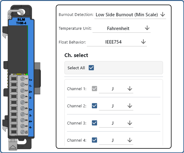
Burnout Detection
The module will monitor the thermocouple for a burnout condition (i.e. open circuit or short circuit) and will perform the following actions to the corresponding channel:
Low Side Burnout: Set the channel to minimum range.
High Side Burnout: Set the channel to maximum range.
Temperature Units
Celsius: °C
Fahrenheit: °F
Float Behavior
This option will determine the format of the data that is returned by the SLM-MX. Both are returned with MSB first.
IEEE-754: This is the default behavior and will return the temperature in 32-bit floating point format across two 16-bit registers.
Integer and Decimal: This will return the temperature in a 16-bit integer and 16-bit decimal format, each in their own register.
Channel Select
Enable or disable the channels to be read. The first channel cannot be disabled.
Thermocouple Type
Select the type of thermocouple to be used.
Modbus Mapping#
Note
The following register mappings assumes that it is the only module connected. Actual mapping may vary depending on the configuration of the system.
Modbus Register Mapping#
Channel |
Modbus Register |
Access |
Register Type |
Data Length |
|---|---|---|---|---|
THM1 |
30001 |
Read-Only |
Input Register |
32-bit |
THM2 |
30003 |
Read-Only |
Input Register |
32-bit |
THM3 |
30005 |
Read-Only |
Input Register |
32-bit |
THM4 |
30007 |
Read-Only |
Input Register |
32-bit |
Notes:
Thermocouple inputs (THM1-THM4) are read-only and correspond to Modbus Input Registers (30001 - 30008).
Each channel are mapped across two 16-bit registers, in IEEE-754 32-bit floating point format or Integer and Decimal (16-bit each).
Each channel supports various thermocouple types for versatile temperature measurement.
Status Register Mapping#
Note: The status registers are read-only booleans and are mapped to Discrete Input Status registers (101001 - 101014).
Status |
Modbus Register |
Access |
Register Type |
Data Length |
|---|---|---|---|---|
Module diagnostics failure |
101001 |
Read-Only |
Input Register |
1-bit |
Module not ready |
101002 |
Read-Only |
Input Register |
1-bit |
Ch1 Burnout |
101003 |
Read-Only |
Input Register |
1-bit |
Ch2 Burnout |
101004 |
Read-Only |
Input Register |
1-bit |
Ch3 Burnout |
101005 |
Read-Only |
Input Register |
1-bit |
Ch4 Burnout |
101006 |
Read-Only |
Input Register |
1-bit |
Ch1 Under Range |
101007 |
Read-Only |
Input Register |
1-bit |
Ch2 Under Range |
101008 |
Read-Only |
Input Register |
1-bit |
Ch3 Under Range |
101009 |
Read-Only |
Input Register |
1-bit |
Ch4 Under Range |
101010 |
Read-Only |
Input Register |
1-bit |
Ch1 Over Range |
101011 |
Read-Only |
Input Register |
1-bit |
Ch2 Over Range |
101012 |
Read-Only |
Input Register |
1-bit |
Ch3 Over Range |
101013 |
Read-Only |
Input Register |
1-bit |
Ch4 Over Range |
101014 |
Read-Only |
Input Register |
1-bit |
Example Usage#
Note
The following examples assume that it is the only module connected. Actual mapping may vary depending on the configuration of the system.
IEEE-754 32-bit Floating Point#
import time
from pyModbusTCP.client import ModbusClient
import struct

client_ip = '192.168.1.255'  # Replace with your device's IP
client = ModbusClient(host=client_ip, port=502, auto_open=True)

while True:
    regs = client.read_input_registers(0, 2)
    combined_int = (regs[1] << 16) | regs[0] #
    float_value = struct.unpack('f', struct.pack('I', combined_int))[0]
    print(float_value)
    time.sleep(1)
#include <ArduinoModbus.h> // Include Modbus library

float readThermocoupleTemp() {
  float temp = 0.0;
  if (!ModbusRTUClient.requestFrom(0x21, INPUT_REGISTERS, 0, 2)) { // Request 2 registers starting at address 0 from slave 0x21
    Serial.print("- Failed to read temperature! ");
    Serial.println(ModbusRTUClient.lastError());
  } else {
    uint16_t highWord = ModbusRTUClient.read(); // Read high word
    uint16_t lowWord = ModbusRTUClient.read();  // Read low word
    uint32_t combinedValue = ((uint32_t)highWord << 16) | lowWord; // Combine into 32-bit value

    // Interpret the 32-bit value as a float (assuming IEEE 754)
    memcpy(&temp, &combinedValue, sizeof(float)); // Copy bytes to temp variable
  }
  return temp;
}
Note
The above code uses the ArduinoModbus library and is not a complete program.
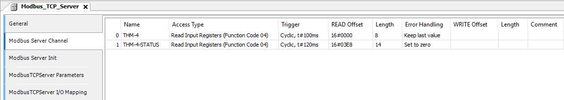
Under Modbus_TCP_Server -> Modbus Server Channel
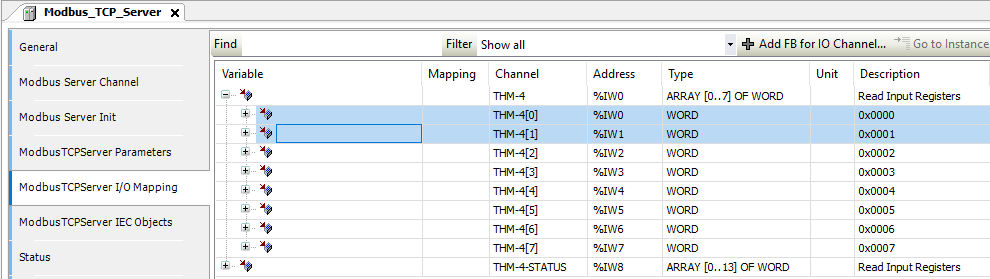
 Under Modbus_TCP_Server -> Modbus Server Channel -> I/O Mapping
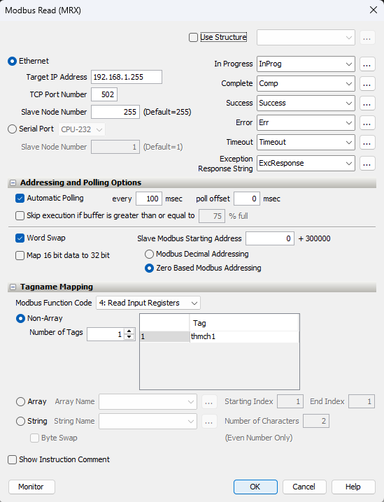
 Usage
Usage
VAR
    THMCH1 AT %IW0 : REAL;
    THMCH2 AT %IW2 : REAL;
END_VAR
Tag
Tag Name |
Type |
|---|---|
thmch1 |
Float, 32 Bit |
Usage
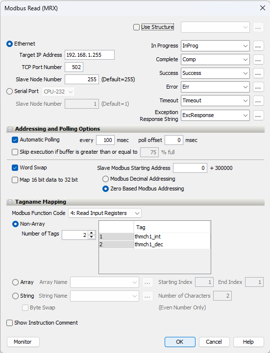
Integer and Decimal#
import time
from pyModbusTCP.client import ModbusClient
import struct

client_ip = '192.168.1.255'  # Replace with your device's IP
client = ModbusClient(host=client_ip, port=502, auto_open=True)

while True:
    ch1 = client.read_input_registers(0, 2)
    ch1_int = ch1[0]
    ch1_dec = ch1[1]
    print("Channel 1 Integer:", ch1_int, "Decimal:", ch1_dec)
    time.sleep(1)
#include <ArduinoModbus.h> // Include Modbus library

int* readThermocoupleTemp() {
  int ch1[2];
  if (!ModbusRTUClient.requestFrom(0x21, INPUT_REGISTERS, 0, 2)) { // Request 2 registers starting at address 0 from slave 0x21
    Serial.print("- Failed to read temperature! ");
    Serial.println(ModbusRTUClient.lastError());
  } else {
    ch1[0] = ModbusRTUClient.read(); // Read integer part
    ch1[1] = ModbusRTUClient.read();  // Read decimal part
  }
  return &ch1;
}
Note
The above code uses the ArduinoModbus library and is not a complete program.
Under Modbus_TCP_Server -> Modbus Server Channel
Under Modbus_TCP_Server -> Modbus Server Channel -> I/O Mapping
Usage
VAR
    THMCH1_INT AT %IW0 : WORD;
    THMCH1_DEC AT %IW1 : WORD;
END_VAR
Tag
Tag Name |
Type |
|---|---|
thmch1_int |
Integer, 16 Bit |
thmch1_dec |
Integer, 16 Bit |
Usage
Specifications#
Safety Precautions#
Do not add or remove modules while field power is applied.
Ensure proper grounding and wire connections to prevent electrical hazards.
Follow all local and national electrical codes.
Maintain adequate ventilation to prevent overheating.
For more details and technical support, visit Synergy Logic or contact support@synergy-logic.com.