Productivity Suite Example Project#
Project Overview#
Before you Start
Before you start, please ensure you have the following:
SLM-MX configured and connected to your network
Basic knowledge of Ladder logic
Project Files#
The Productivity Suite project file, as well as the SLM-MX configuration file can be found in the zip file here.
Please download and extract the zip file to a easily accessible directory.
Hardware Configuration#
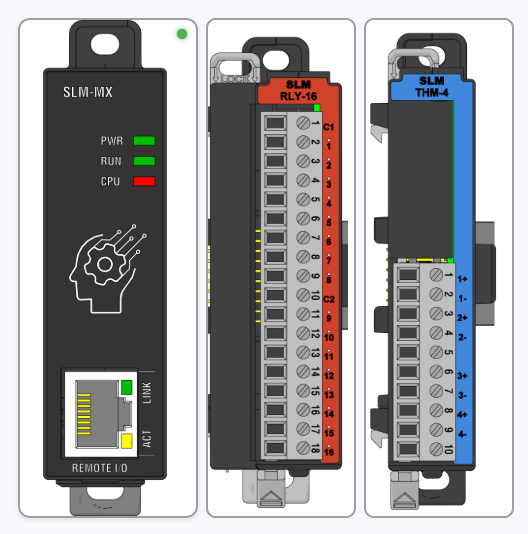
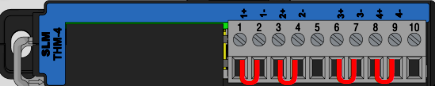
The slots used in this example were the same as those shown in the photo above.
Module 1: SLM-RLY-16 Module 2: SLM-THM-4
Module Configuration#
For the example to work correctly, your MX must have the respective slots connected. After that, click the configure button so that the MX maps the slots found in the Modbus register table.
Please refer to the Importing Configuration Files page for instructions on how to import the configuration file.
Software Configuration#
The version of Productivity Suite used for this project is 4.2.0(19).
The target platform is a Windows 11 machine running Productivity Suite, essentially using the PC as the main controller with the SLM-MX as the remote I/O module.
This also keeps the project easy to deploy to any PC with Productivity Suite installed.
Importing the project#
You can import the project by first extracting the zip file into a easily accessible directory.
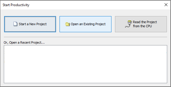
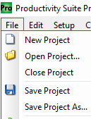
Open Productivity Suite and select Open an Existing Project, or File and Open Project.
Browse to the imported ProSuiteDemo.adpro project, select it, and click Open.
Project Configuration#
With the Example project imported, you should see the tasks populated as shown below.
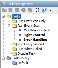
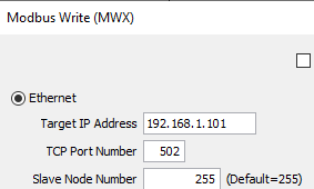
Double click the Modbus Control task, open each Modbus instruction, and update the Target IP Address to match your SLM-MX Configurator IP address.
CPU Connection#
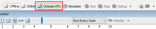
Connect to your Productivity CPU by clicking on the Choose CPU button.
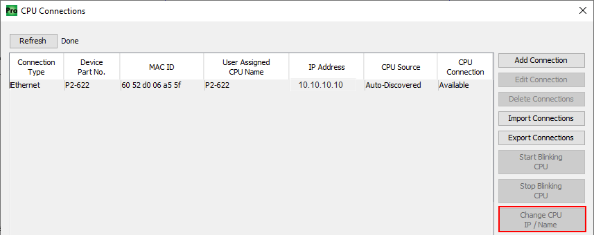
A CPU Connections window will pop up. The Default IP Address will be 10.10.10.10.
Click the Change CPU Ip/Name button.
Check the Optain Address from DHCP box or add a static IP.
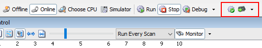
Transfer the example project by clicking on the Green arrow.
Project Tasks Overview#
Modbus Control: The Sequencer instruction is used to enable and cycle through each Modbus Instruction. Each step enables a NO contact that triggers a Modbus Write/Read operation. The Sequencer moves to the next step when a Success bit for the current instruction is True or if the elaspsed Duration has occured.
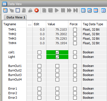
Light Control: Channel one of the SLM-THM-4 is being monitored for temperature. When it reaches 75 degrees Fahrenheit or higher, coil1 of the SLM-RLY-16 will turn on, triggering a light to turn on. If the temperature goes below 75 degrees Fahrenheit, the coil and light will turn off.
Error Handling: The Pack Bits instruction is used to combine all Modbus Write/Read Error bits and SLM-THM-4 Burnout bits. Compare instructions are used to check the state of the bits. Set Cools are activated upon a failure.
Running the Example#
Note: The -/+ of each channel of the SLM-THM-4 are shorted to read the ambiant temperature.
Place the CPU into Run mode by using either the Run-Stop switch of the CPU or Run button in Productivity Suite to start the example project.
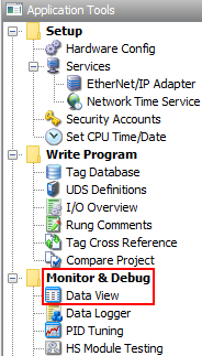
On the Application Tools pane on the left, expand the Monitor and Debug section and select Dataview
The temperature threshold can be adjusted for your enviroment by editing the compare contact of rung 1, column 5 of the Light Control task.
Error Handling#
The burnout bits of the SLM-THM-4 can be tested by removing the terminal.
A CPU Stop/Run transition resets the Set Coils.